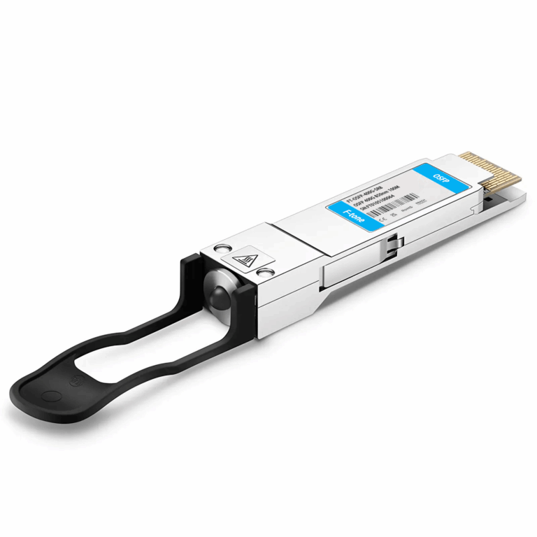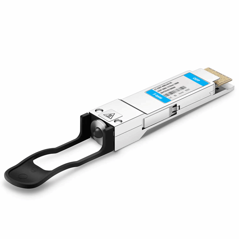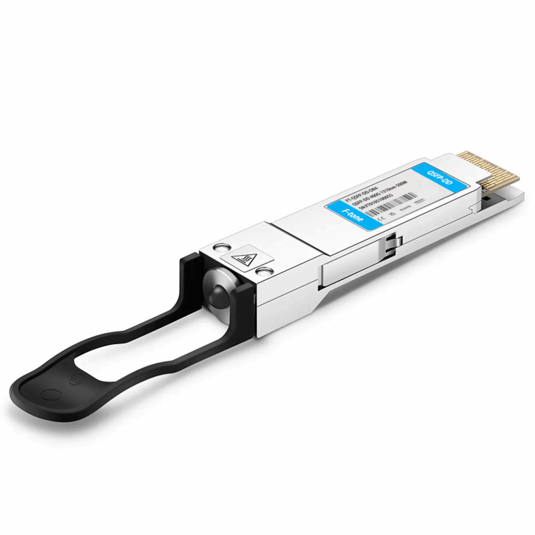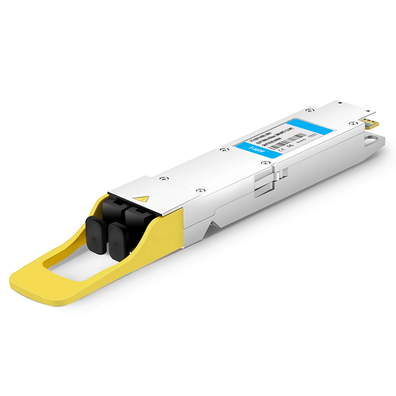
Features
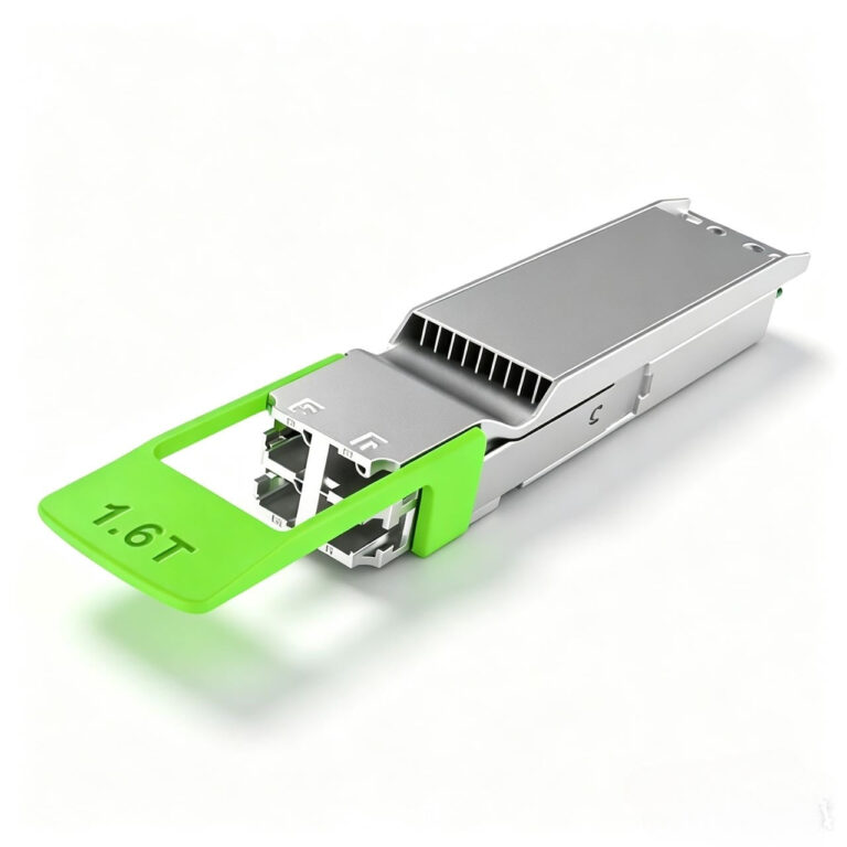
- Form Factor: Hot-pluggable OSFP800 form factor
- Data Rate: Aggregate data rate of 850 Gb/s and Breakout data rate of 106.25 Gb/s
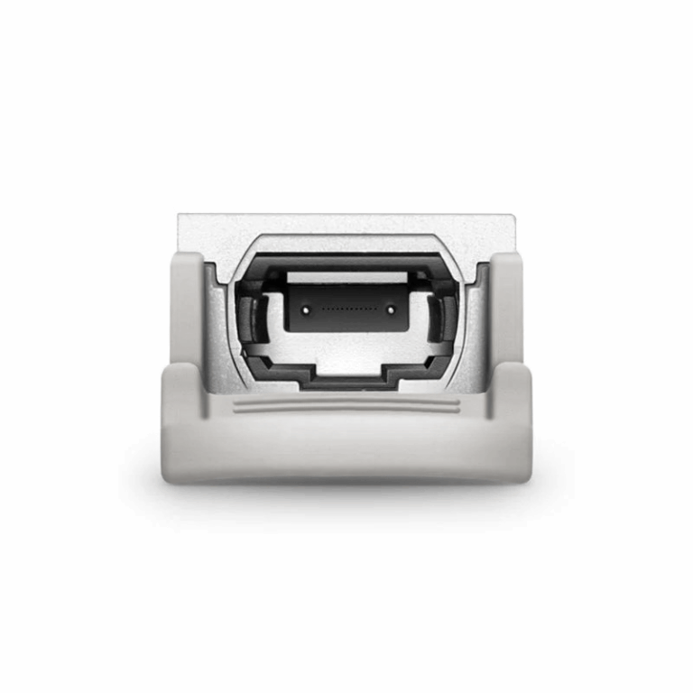
- Optical Interface: Compliant to 2×400GBASE-DR4 and 8x100GBASE-DR
- Electrical Interface: Compliant to 2×400GAUI-4 and 8x100GAUI-1
- Management Interface: I2C management interface
- Reach: Up to 500m over MPO/APC single mode fiber
- Power consumption: 16 W max
- Operating case temperature: 0 ~ 70 ℃
- Power Supply: Single 3.3V power supply
Compliance
- Form Factor: OSFP MSA Rev 5.0
- Optical: IEEE802.3cd /IEEE802.3bs
- Electrical: IEEE802.3ck
- Firmware: CMIS 5.2
- Environment: RoHS
- Stability: GR-468-CORE
Applications
- 800Gb/s Ethernet
- Data Center
OSFP 800G DR8 SM MPO12 IB Transceiver
NVIDIA twin port transceiver
800G ,2xNDR, OSFP, 2xMPO12 APC, 1310nm SMF, up to 100m, finned.
Functional Block Diagram
General Description
The 800G OSFP DR8 are high-performance, cost-effective transceivers designed for utilization in 800 Gigabit Ethernet links over 500 meters. On transmitter side, the module converts eight channels of 53.125 GBaud (PAM4) electrical data to eight channels of parallel optical signals with data rate of 53.125 GBaud (PAM4). At receiver side, the module converts eight channels of parallel optical signals with data rate of 53.125 GBaud (PAM4) into eight channels of 53.125 GBaud(PAM4) electrical output data.
The product is designed according to the OSFP MSA. It is designed to meet the harshest external operating conditions including temperature, humidity and EMI interference.
Absolute Maximum Ratings and Recommended Operating Conditions
Absolute Maximum Ratings
|
Parameter |
Symbol |
Min |
Typical |
Max |
Unit |
|
Storage Temperature |
Ts |
-40 |
|
85 |
°C |
|
Relative Humidity (non-condensation) |
FH |
15 |
|
85 |
% |
|
Supply Voltage |
Vcc |
-0.5 |
|
3.6 |
V |
|
Optical Input Power, per Lane |
PIN |
|
|
5.0 |
dBm |
Recommended Operating Conditions
|
Parameter |
Symbol |
Min |
|
Max |
Unit |
|
Operating Case Temperature |
TC |
0 |
|
70 |
°C |
|
Signaling Rate, each lane |
|
|
53.125 |
|
GBd |
|
Data Rate Accuracy |
|
-100 |
|
100 |
ppm |
|
Power Supply Voltage |
VCC |
3.135 |
3.3 |
3.465 |
V |
|
Pre-FEC Bit Error Ratio |
|
|
|
2.4E-4 |
|
|
Transmission Distance |
|
|
|
500 |
m |
Optical Specifications
Optical Transmitter
Transmitter optical characteristics
|
Parameter |
Symbol |
Min |
Typical |
Max |
Unit |
|
Signaling rate, each lane |
SR |
53.125+/-100ppm |
GBd |
||
|
Modulation format |
|
PAM4 |
|
||
|
Lane wavelength |
λ |
1304.5 |
1311.0 |
1317.5 |
nm |
|
Side-mode suppression ratio |
SMSR |
30 |
|
|
dB |
|
Average launch power, each lanea |
AOPTX |
-2.9 |
|
4.0 |
dBm |
|
Outer Optical Modulation Amplitude (OMAouter), each laneb |
OMATX |
-0.8 |
|
|
dBm |
|
Launch power in OMAouter minus TDECQ, each lane |
|
-2.2 |
|
|
dBm |
|
Transmitter and dispersion eye closure for PAM4, each lane |
TDECQ |
|
|
3.4 |
dB |
|
Average launch power of OFF transmitter, each lane |
AOPOFF |
|
|
-15 |
dBm |
|
Extinction ratio, each lane |
ER |
3.5 |
|
|
dB |
|
FIN21.4OMA |
|
|
|
–136 |
dB/Hz |
|
Optical return loss tolerance |
FLTol |
|
|
21.4 |
dB |
|
Transmitter reflectancec |
Reflectance_ Tx |
|
|
-26 |
dB |
Note:
a. Average launch power, each lane (min) is informative and not the principal indicator of signal strength. A transmitter with launch power below this value cannot be compliant; however, a value above this does not ensure compliance.
b. Even if the TDECQ < 1.4 dB, the OMAouter (min) must exceed these values.
c. Transmitter reflectance is defined looking into the transmitter.
3.2 Optical Receiver
Receiver optical characteristics
|
Parameter |
Symbol |
Min |
Typical |
Max |
Unit |
|
|
Signaling rate, each lane |
SR |
53.125+/-100ppm |
GBd |
|||
|
Modulation format |
|
PAM4 |
– |
|||
|
Lane wavelengths |
λ |
1304.5 |
1311.0 |
1317.5 |
nm |
|
|
Damage threshold, each lanea |
DThd |
5 |
|
|
dBm |
|
|
Average receive power, each laneb |
AOPRX |
-5.9 |
|
4 |
dBm |
|
|
Receiver reflectance |
Reflectance_ Rx |
|
|
-26 |
dB |
|
|
Receiver sensitivity (OMAouter), each lanec |
RxSens |
|
|
-4.4 |
dBm |
|
|
Stressed receiver sensitivity (OMAouter), each laned |
SRS |
|
|
-1.9 |
dBm |
|
|
Conditions of stressed receiver sensitivity test:e |
||||||
|
Stressed eye closure for PAM4 (SECQ), lane under test |
|
|
3.4 |
|
dB |
|
|
OMAouter of each aggressor lane |
|
|
4.2 |
|
dBm |
|
|
Rx LOS |
LOS Assert |
LOSA |
-15 |
|
-7.9 |
dBm |
|
LOS De-assert |
LOSD |
|
|
-7.4 |
dBm |
|
|
LOS Hysteresis |
LOSH |
0.5 |
|
5 |
dB |
|
Notes:
a. The receiver shall be able to tolerate, without damage, continuous exposure to an optical input signal having this average power level. The receiver does not have to operate correctly at this input power.
b. Average receive power, each lane (min) is informative and not the principal indicator of signal strength. A received power below this value cannot be compliant; however, a value above this does not ensure compliance.
c. Receiver sensitivity (OMAouter), each lane (max) is informative and is defined for a transmitter with SECQ of 0.9 dB.
d. Measured with conformance test signal at TP3 for the BER = 2.4E-4.
e. These test conditions are for measuring stressed receiver sensitivity. They are not characteristics of the receiver.
Digital Diagnostic Monitor Accuracy
The following characteristics are defined over recommended operating conditions.
|
Parameter |
Accuracy |
Unit |
|
Internally Measured Transceiver Temperature |
+/-3 |
℃ |
|
Internally Measured Transceiver Supply Voltage |
+/-3 |
% |
|
Measured Tx Bias Current |
+/-10 |
% |
|
Measured Tx Output Power |
+/-3 |
dB |
|
Measured Rx Received Average Optical Power |
+/-3 |
dB |
Pin Assignment and Description
The OSFP module pinout and connector pin list are as follows:
Mechanical Dimensions
Package dimensions in mm are specified in OSFP MSA.
Package dimensions
Ordering Information
|
Part Number |
Temperature Range |
Distance |
Media Connector |
Fiber Type |
E/O |
O/E |
|
F12OSFP-800G-DR8 |
0 to 70℃ |
500m |
Dual MPO-12 |
SMF |
Siph PIC |
Siph PD |
|
F16OSFP-800G-DR8 |
0 to 70℃ |
500m |
MPO-16 |
SMF |
Siph PIC |
Siph PD |
工作温度:商业级/工业级/军品级可选
本产品为 北亿纤通 | F-tone Networks FT-81系列产品线,详细信息,请联系我们的销售人员,谢谢!Important Notice Performance figures, data and any illustrative material provided in this data sheet are typical and must be specifically confirmed in writing by Andxe System before they become applicable to any particular order or contract. In accordance with the Andxe System policy of continuous improvement specifications may change without notice.The publication of information in this data sheet does not imply freedom from patent or other protective rights of Andxe System or others. Further details are available from any Andxe System sales representative.