Features
- IEEE 802.3bs Specification compliant
- QSFP-DD MSA compliant
- 4×106.25 Gbps PAM4 optical interface
- 8×53.125 Gbps PAM4 electrical interface
- I2C interface with integrated DDM
- Up to 2km transmission distance on single mode fiber (SMF) with FEC
- up ply voltage: 3.3 V
- Maximum power consumption: 12 W
- MTP/MPO-12 connector
- Operating case temperature: 0 to 70 °C
- RoHS compliant
Applications
- 400G Ethernet
- Datacenter enterprise networking
FQDD-400G-EDR4
400Gbps QSFP-DD EDR4 2KM EML MPO transceiver
General description
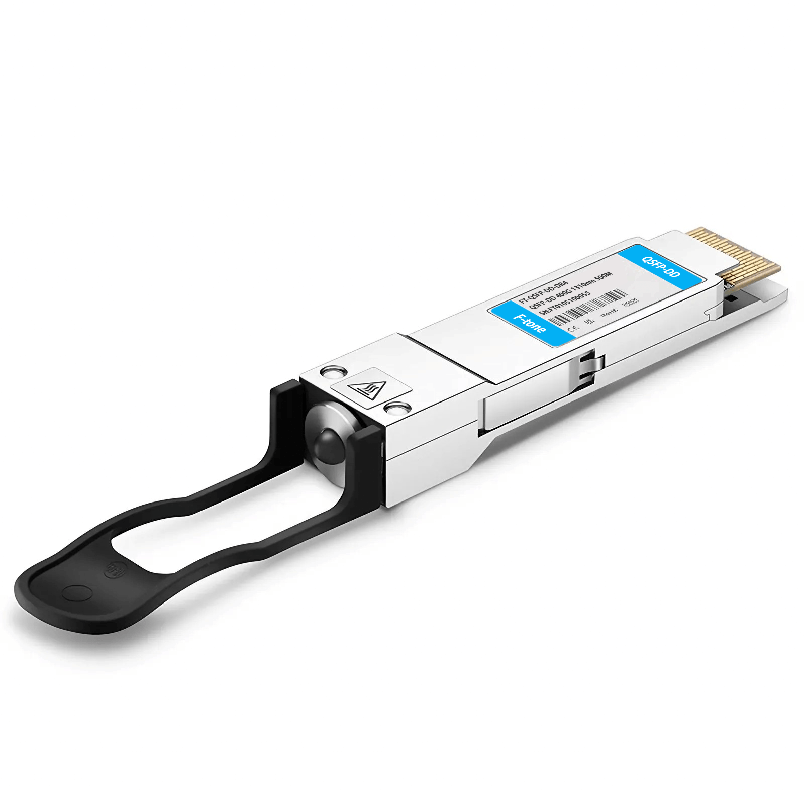
FQDD-400G-EDR4 is a 400 Gbps Quad Small Form Factor Pluggable-Double Density (QSFP-DD) optical transceiver designed for 2km optical communication applications.
Functional description
ModSelL is an input pin. When held low by the host, this product responds to 2-wire serial communication commands. ResetL is a signal that allows the host to reset the module. A low level on the ResetL signal for longer than the minimum pulse length initiates a complete modulele reset, returning all all user module setting Sule settings tos to their default state. LPMode/TxDis is an input signal from the host operating with active high logic. If this pin is “high”, the module enters a low-power state. ModPrsL is used to indicate whether the module is plugged in on the connector, ModPrsL is pulled low when inserted and released to high when it is physically absent from the host connector. IntL/RxLOSL pin is used as interruption. When “Low”, it indicates a possible module operational fault, such as alarm and warning.
Absolute maximum ratings
It has to be noted that the operation in excess of any individual absolute maximum ratings might cause permanent damage to this module.
|
Parameter |
Symbol |
Min |
Max |
Unit |
Note |
|
Storage Temperature |
TS |
-40 |
85 |
°C |
|
|
Operating Case Temperature |
TOP |
0 |
70 |
°C |
|
|
Power Supply Voltage |
VCC |
-0.5 |
3.6 |
V |
|
|
Relative Humidity (non-condensation) |
FH |
0 |
85 |
% |
|
Recommended operating conditions
| Parameter | Symbol | Min | Typical | Max | Unit | Note |
| Operating Case Temperature | TOP | 0 | 70 | °C | ||
|
Power Supply Voltage |
VCC |
3.135 |
3.3 |
3.465 |
V |
|
|
Power Consumption |
|
|
|
12 |
W |
|
|
Supply Current |
Icc |
|
|
3.64 |
A |
|
|
Pre-FECBitError Ratio |
|
|
|
2.4×10⁻⁴ |
|
|
|
Post-FECBitError Ratio |
|
|
|
1×10-12 |
|
1 |
|
Link Distance |
D |
|
|
2 |
km |
2 |
Notes:
1. FEC provided by host system.
2. FEC required on host system to support maximum distance.
Digital diagnostic functions
The following digital diagnostic characteristics are defined over the normal operating conditions unless otherwise specified.
|
Parameter |
Symbol |
Min |
Max |
Unit |
Note |
|
Temperature Monitor Absolute Error outer Error |
DMI_Temp |
-3 |
3 |
°C |
Cover full operating temperature range |
|
Supply Voltage Monitor Absolute ErroruteError |
DMI _VCC |
-0.1 |
0.1 |
V |
Cover full operating temperature range |
|
Channel FX Power Monitor Absolute ErrorteError |
DMI_RX_Ch |
-3 |
3 |
dB |
|
|
Channel Bias Current Monitor |
DMI_Ibias_Ch |
-10% |
10% |
|
|
|
Channel TX Power Monitor Absolute Error |
DMI_TX_Ch |
-3 |
3 |
dB |
|
Edge connector and pinout description
The electrical pinout of the QSFP-DD module is shown in Figure 1 below.
MSA compliant connector.
Mechanical dimensions
Mechanical outline
Ordering information
|
Part Number |
Product Description |
|
FQDD-400G-EDR4 |
400G QSFP-DD EDR4 2KM EML MPO |
工作温度:商业级/工业级/军品级可选
本产品为 北亿纤通 | F-tone Networks FT-81系列产品线,详细信息,请联系我们的销售人员,谢谢!Important Notice Performance figures, data and any illustrative material provided in this data sheet are typical and must be specifically confirmed in writing by Andxe System before they become applicable to any particular order or contract. In accordance with the Andxe System policy of continuous improvement specifications may change without notice.The publication of information in this data sheet does not imply freedom from patent or other protective rights of Andxe System or others. Further details are available from any Andxe System sales representative.