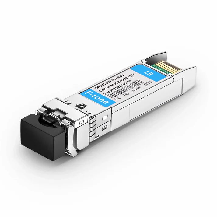
Features:
- 4 CWDM lanes MUX/DEMUX design
- Cooled CWDM DFB transmitter
- Up to 11.2Gbps per channel bandwidth
- Aggregate bandwidth of > 40Gbps
- Duplex LC connector
- Compliant with 40G Ethernet IEEE802.3ba and 40GBASE-LR4 Standard and OTU3 for line rate of 43Gbps
- QSFP MSA compliant
- Up to10km transmission
- Compliant with QDR/DDR InfiniBand data rates
- Single +3.3V power supply operating
- Built-in digital diagnostic functions
- RoHS Compliant Part
Applications:
- Rack to rack
- Data centers Switches and Routers
- Metro networks
- Switches and Routers
- 40G BASE-LR4 Ethernet Links
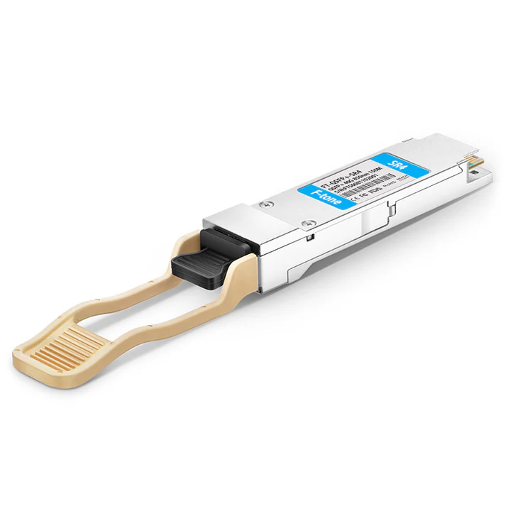
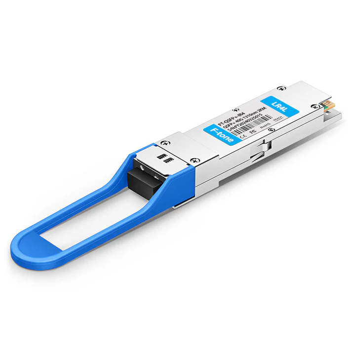
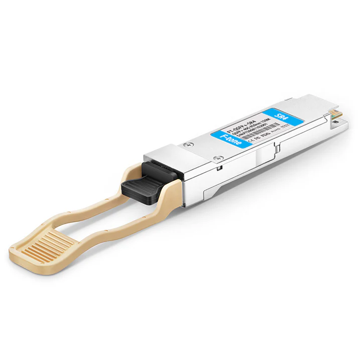
FQ-40G-LR4I
40Gb/s 10km QSFP+ Transceiver Hot Pluggable, Duplex LC Connector, Single mode
Description:
The FQ-40G-LR4I is a transceiver module designed for 10km optical communication applications. The design is compliant to 40GBASE-LR4 of the IEEE P802.3ba standard. The module converts 4 inputs channels (ch) of 10Gb/s electrical data to 4 CWDM optical signals, and multiplexes them into a single channel for 40Gb/s optical transmission. Reversely, on the receiver side, the module optically DE-multiplexes a 40Gb/s input into 4 CWDM channels signals, and converts them to 4 channel output electrical data.
The central wavelengths of the 4 CWDM channels are 1271, 1291, 1311 and 1331 nm as members of the CWDM wavelength grid defined in ITU-T G694.2. It contains a duplex LC connector for the optical interface and a 38-pin connector for the electrical interface. To minimize the optical dispersion in the long-haul system, single-mode fiber (SMF) has to be applied in this module.
The product is designed with form factor, optical/electrical connection and digital diagnostic interface according to the QSFP Multi-Source Agreement (MSA). It has been designed to meet the harshest external operating conditions including temperature, humidity and EMI interference.
The module operates from a single +3.3V power supply and LVCMOS/LVTTL global control signals such as Module Present, Reset, Interrupt and Low Power Mode are available with the modules. A 2-wire serial interface is available to send and receive more complex control signals and to obtain digital diagnostic information. Individual channels can be addressed and unused channels can be shut down for maximum design flexibility.
The FQ-40G-LR4I is designed with form factor, optical/electrical connection and digital diagnostic interface according to the QSFP Multi-Source Agreement (MSA). It has been designed to meet the harshest external operating conditions including temperature, humidity and EMI interference. The module offers very high functionality and feature integration, accessible via a two-wire serial interface.
Absolute Maximum Ratings
|
Parameter |
Symbol |
Min. |
Typical |
Max. |
Unit |
|
Storage Temperature |
TS |
-40 |
|
+85 |
°C |
|
Supply Voltage |
VCCT, R |
-0.5 |
|
4 |
V |
|
Relative Humidity |
FH |
0 |
|
85 |
% |
Recommended Operating Environment:
|
Parameter |
Symbol |
Min. |
Typical |
Max. |
Unit |
|
Case operating Temperature |
TC |
-40 |
|
+85 |
°C |
|
Supply Voltage |
VCCT, R |
+3.13 |
3.3 |
+3.47 |
V |
|
Supply Current |
ICC |
|
|
1000 |
mA |
|
Power Dissipation |
PD |
|
|
3.5 |
W |
Electrical Characteristics (TOP = -40°C to 85°C, VCC = 3.13 to 3.47 Volts)
|
Parameter |
Symbol |
Min |
Typ |
Max |
Unit |
Note |
|
Data Rate per Channel |
|
– |
10.3125 |
11.2 |
Gbps |
|
|
Power Consumption |
|
– |
2.5 |
3.5 |
W |
|
|
Supply Current |
Icc |
|
0.75 |
1.0 |
A |
|
|
Control I/O Voltage-High |
VIH |
2.0 |
|
Vcc |
V |
|
|
Control I/O Voltage-Low |
VIL |
0 |
|
0.7 |
V |
|
|
Inter-Channel Skew |
TSK |
|
|
150 |
Ps |
|
|
FESETL Duration |
|
|
10 |
|
Us |
|
|
FESETL De-assert time |
|
|
|
100 |
ms |
|
|
Power On Time |
|
|
|
100 |
ms |
|
|
Transmitter |
||||||
|
Single Ended Output Voltage Tolerance |
|
0.3 |
|
4 |
V |
1 |
|
Common mode Voltage Tolerance |
|
15 |
|
|
mV |
|
|
Transmit Input Diff Voltage |
VI |
150 |
|
1200 |
mV |
|
|
Transmit Input Diff Impedance |
ZIN |
85 |
100 |
115 |
|
|
|
Data Dependent Input Jitter |
DDJ |
|
0.3 |
|
UI |
|
|
Receiver |
||||||
|
Single Ended Output Voltage Tolerance |
|
0.3 |
|
4 |
V |
|
|
Rx Output Diff Voltage |
Vo |
370 |
600 |
950 |
mV |
|
|
Rx Output Rise and Fall Voltage |
Tr/Tf |
|
|
35 |
ps |
1 |
|
Total Jitter |
TJ |
|
0.3 |
|
UI |
|
Note:
1. 20~80%
Optical Parameters (TOP = -40°C to 85°C, VCC = 3.0 to 3.6 Volts)
|
Parameter |
Symbol |
Min |
Typ |
Max |
Unit |
Ref. |
|
Transmitter |
||||||
|
Wavelength Assignment |
L0 |
1264.5 |
1271 |
1277.5 |
nm |
|
|
L1 |
1284.5 |
1291 |
1297.5 |
nm |
|
|
|
L2 |
1304.5 |
1311 |
1317.5 |
nm |
|
|
|
L3 |
1324.5 |
1331 |
1337.5 |
nm |
|
|
|
Side-mode Suppression Ratio |
SMSR |
30 |
– |
– |
dB |
|
|
Total Average Launch Power |
PT |
|
– |
8.3 |
dBm |
|
|
Average Launch Power, each Lane |
|
-7 |
– |
2.3 |
dBm |
|
|
Transmit OMA per Lane |
TxOMA |
-6 |
|
3.5 |
dBm |
|
|
Difference in launch power between any two lanes (OMA) |
|
|
|
4.7 |
dBm |
|
|
Transmitter Dispersion Penalty each Lane |
TDP |
|
|
2.0 |
dB |
|
|
Extinction Ratio |
ER |
3.5 |
5 |
|
dB |
|
|
Extinction Ratio |
ER |
3.5 |
– |
– |
dB |
|
|
Transmitter Eye Mask Definition {X1, X2, X3, Y1, Y2, Y3} |
|
{0.25, 0.4, 0.45, 0.25, 0.28, 0.4} |
|
|
|
|
|
Optical Return Loss Tolerance |
|
– |
– |
20 |
dB |
|
|
Average Launch Power OFF Transmitter, each Lane |
Poff |
|
|
-30 |
dBm |
|
|
Relative Intensity Noise |
Rin |
|
|
-128 |
dB/HZ |
1 |
|
Optical Return Loss Tolerance |
|
– |
– |
12 |
dB |
|
|
Receiver |
||||||
|
Damage Threshold |
THd |
3.3 |
|
|
dBm |
1 |
|
Average Power at Receiver Input, each Lane |
R |
-14 |
|
3 |
dBm |
|
|
Receive Electrical 3 dB upper Cut off Frequency, each Lane |
|
|
|
12.3 |
GHz |
|
|
FSSI Accuracy |
|
-2 |
|
2 |
dB |
|
|
Receiver Reflectance |
Rrx |
|
|
-26 |
dB |
|
|
Receiver Power (OMA), each Lane |
|
– |
– |
3.5 |
dBm |
|
|
Receive Electrical 3 dB upper Cutoff Frequency, each Lane |
|
|
|
12.3 |
GHz |
|
|
LOS De-Assert |
LOSD |
|
|
-15 |
dBm |
|
|
LOS Assert |
LOSA |
-30 |
|
|
dBm |
|
|
LOS Hysteresis |
LOSH |
0.5 |
|
|
dB |
|
Note
1. 12dB Reflection
Mechanical Dimensions
工作温度:商业级/工业级/军品级可选
本产品为 北亿纤通 | F-tone Networks FT-81系列产品线,详细信息,请联系我们的销售人员,谢谢!Important Notice Performance figures, data and any illustrative material provided in this data sheet are typical and must be specifically confirmed in writing by Andxe System before they become applicable to any particular order or contract. In accordance with the Andxe System policy of continuous improvement specifications may change without notice.The publication of information in this data sheet does not imply freedom from patent or other protective rights of Andxe System or others. Further details are available from any Andxe System sales representative.